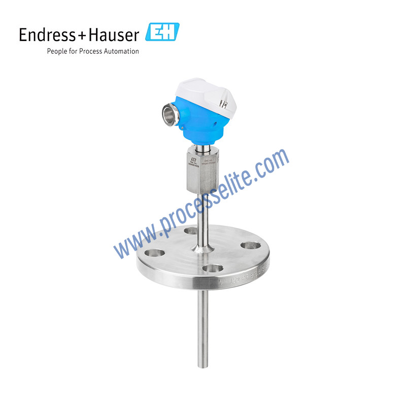
The working principle of Resistance Temperature Detector (RTD) is temperature measurement based on the property that the resistance of metallic conductors varies with temperature. Core principle: as temperature changes, the lattice‑vibration amplitude of metallic conductors such as platinum and copper changes, which causes varying obstruction to electron movement and a corresponding change in resistance. Taking Pt100 platinum RTD as an example, its nominal resistance is 100 Ω at 0 °C; resistance increases by approximately 0.385 Ω for every 1 °C rise in temperature, showing highly linear behaviour within a certain temperature range. In practical measurement, a constant‑current source or bridge circuit converts resistance variations into electrical signals. Three‑wire / four‑wire connection is used to eliminate lead‑wire errors. Resistance values are finally converted to temperature values according to international standard reference tables.
Thermocouples feature simple construction and high robustness. Thermocouple sensors measure temperature based on the Seebeck effect. Two dissimilar conductors are connected to form a closed loop. A tiny voltage difference arises in the loop when temperatures differ at the two junctions. This voltage difference is referred to as thermoelectric voltage or thermoelectromotive force. Its magnitude depends on the materials of the two conductors and the temperature difference between the “measuring junction” (the joint of the two conductors) and the “cold junction” (open ends of the conductors). For this reason, thermocouples are normally used for differential‑temperature measurement. The absolute temperature at the measuring junction can be obtained if the cold‑junction temperature is known, or measured separately for compensation. Standards IEC 60584 and ASTM E230/ANSI MC96.1 list common thermocouple conductor material combinations and their corresponding thermoelectric‑voltage‑temperature characteristics.